Project Ogre Part 3: Building Maps with SLAM
Building Maps with SLAM
This is Part 3 of the Project Ogre series. In Part 1, we built the mecanum drive robot, and in Part 2, we created a digital twin in Isaac Sim. Now we'll use both to build maps using SLAM (Simultaneous Localization and Mapping).
Project Goal: Create accurate occupancy grid maps using slam_toolbox that can be used for autonomous navigation with Nav2.
📦 Full Source Code: All ROS2 packages and configuration files are available at github.com/protomota/ogre-slam
The video below shows SLAM mapping in action. On the left is RViz displaying the occupancy grid map as it's being built in real-time. On the right is Isaac Sim where I'm teleoperating the simulated robot around the maze. As the robot explores, the LIDAR scans are processed by slam_toolbox to incrementally construct the map.
What is SLAM?
SLAM (Simultaneous Localization and Mapping) solves a chicken-and-egg problem: to know where you are, you need a map. To build a map, you need to know where you are. SLAM algorithms solve both simultaneously by matching sensor data against an incrementally-built map.
For Project Ogre, we use slam_toolbox - a robust 2D SLAM implementation that works well with LIDAR sensors. It takes laser scan data from the RPLIDAR and odometry estimates from our encoders, then produces:
- A map (occupancy grid showing obstacles and free space)
- A localization estimate (where the robot is on that map)
The Two-Computer Setup
Project Ogre uses a split architecture:
Host Computer (Development)
- Runs NVIDIA Isaac Sim for simulation
- Runs RViz for visualization
- Handles resource-intensive debugging
Jetson Orin Nano (Robot)
- Runs on the physical robot
- Handles real sensor data
- Executes navigation commands
Both computers use the same ROS_DOMAIN_ID to communicate over the network. This lets me visualize the robot's SLAM progress in RViz on my development machine while the actual processing happens on the Jetson.
Configuring slam_toolbox
The SLAM configuration lives in config/slam_toolbox_params.yaml. Here are the key parameters tuned for Project Ogre's hardware:
Frame Configuration
odom_frame: odom
map_frame: map
base_frame: base_link
scan_topic: /scan
mode: mapping
These define the TF frames SLAM uses and where it gets laser scan data.
Scan Processing
transform_publish_period: 0.02    # 50 Hz TF publishing
map_update_interval: 2.0          # Update map every 2 seconds
resolution: 0.05                  # 5cm grid cells
max_laser_range: 12.0             # RPLIDAR A1 max range
minimum_time_interval: 0.2        # Minimum time between scans
The map_update_interval and resolution are tuned for the Jetson's memory constraints. Publishing the map every 2 seconds instead of continuously reduces CPU load significantly.
Critical: Minimum Travel Thresholds
minimum_travel_distance: 0.0
minimum_travel_heading: 0.0
These are set to zero on purpose. By default, slam_toolbox only processes new scans when the robot has moved a minimum distance or rotated a minimum angle. With our noisy 2 PPR encoders, this caused issues - the map would stop updating because odometry drift made SLAM think the robot hadn't moved.
Setting both to 0.0 forces SLAM to process scans based on time only (minimum_time_interval), not odometry.
Scan Matching Parameters
correlation_search_space_dimension: 2.0
correlation_search_space_resolution: 0.01
distance_variance_penalty: 0.3
angle_variance_penalty: 0.5
These control how SLAM matches new scans against the existing map. Lower variance penalties mean "trust scan matching more than odometry." Given our encoder limitations, we want SLAM to rely more heavily on the LIDAR data.
Loop Closure
do_loop_closing: true
loop_search_maximum_distance: 6.0
loop_match_minimum_response_coarse: 0.45
loop_match_minimum_response_fine: 0.55
Loop closure happens when the robot revisits a previously-seen location. SLAM recognizes the overlap and corrects accumulated drift. These parameters balance between catching real loop closures and avoiding false positives.
Mapping in Isaac Sim
Before mapping with the real robot, I develop and test in Isaac Sim. This catches configuration issues without burning through battery life or risking hardware damage.
Step 1: Start Isaac Sim
Load the usds/ogre.usd scene and verify the ROS2 Context node has a matching Domain ID. Press Play to start the simulation.
Step 2: Launch SLAM
cd ~/ros2_ws
source install/setup.bash

ros2 launch ogre_slam mapping.launch.py \
  use_rviz:=true \
  use_teleop:=false \
  use_odometry:=false \
  use_ekf:=false \
  use_sim_time:=true
Note the flags:
use_sim_time:=true- Sync with Isaac Sim's clockuse_odometry:=false- Isaac Sim provides odometry directlyuse_ekf:=false- Simulated odometry is clean, no filtering needed
Step 3: Launch the Policy Controller
The policy controller converts Twist commands to individual wheel velocities:
ros2 launch ogre_policy_controller policy_controller.launch.py
Step 4: Drive and Map
ros2 run teleop_twist_keyboard teleop_twist_keyboard \
  --ros-args -r /cmd_vel:=/cmd_vel_smoothed
Drive slowly around the environment. Watch RViz as the map builds in real-time. Make sure to create loop closures by revisiting your starting position.
Step 5: Save the Map
ros2 run nav2_map_server map_saver_cli \
  -f ~/ros2_ws/src/ogre-slam/maps/isaac_sim_map
This creates two files:
isaac_sim_map.yaml- Metadata (resolution, origin, etc.)isaac_sim_map.pgm- The actual map image
Mapping on the Real Robot
Once SLAM works in simulation, deploying to the Jetson is straightforward:
Step 1: Launch the Mapping Session
SSH into the robot and run:
cd ~/ros2_ws/src/ogre-slam
./scripts/launch_mapping_session.sh
This unified script launches:
- RPLIDAR driver
- Encoder-based odometry node
- EKF sensor fusion
- slam_toolbox (mapping mode)
- Web teleop interface
Step 2: Drive via Web Interface
Open a browser on any device on the network:
http://10.21.21.45:8080
The web interface provides joystick-style control. Drive slowly and smoothly - jerky movements confuse the encoder-based odometry.
Tips for Good Maps:
- Move at consistent, slow speeds
- Avoid wheel slippage (especially on smooth floors)
- Create multiple loop closures
- Drive the same area from different angles
Step 3: Save the Map
ros2 run nav2_map_server map_saver_cli \
  -f ~/ros2_ws/src/ogre-slam/maps/my_map
Remote Visualization
Running RViz on the Jetson consumes resources needed for SLAM. Instead, run RViz remotely:
On the robot:
ros2 launch ogre_slam mapping.launch.py use_rviz:=false
On your development machine:
cd ~/ros2_ws/src/ogre-slam
./scripts/remote_launch_slam_rviz.sh
The script sets up the ROS_DOMAIN_ID and launches RViz with pre-configured displays for:
- LaserScan (
/scan) - Map (
/map) - TF frames
- Robot footprint
Troubleshooting
Map Not Updating
Symptom: RViz shows an empty or frozen map
Cause: Usually odometry issues. slam_toolbox needs meaningful position changes to trigger scan processing.
Solution:
- Verify
/odomshows changing positions when driving:ros2 topic echo /odom --once | grep -A 3 "position" - Check gear_ratio calibration (Part 1)
- Ensure
minimum_travel_distance: 0.0in config
SLAM Losing Track
Symptom: Map suddenly rotates or shifts incorrectly
Cause: Scan matching failed, possibly from driving too fast or odometry drift
Solution:
- Drive slower
- Increase
scan_buffer_sizefor more reference scans - Lower
link_match_minimum_response_fineto accept weaker matches
High CPU Usage
Symptom: Jetson running hot, sluggish response
Solution:
- Increase
map_update_interval(try 3.0 or 5.0 seconds) - Increase
resolution(0.10 instead of 0.05) - Disable RViz on the Jetson
No Loop Closure
Symptom: Drift accumulates, map doesn't correct when revisiting areas
Solution:
- Ensure
do_loop_closing: true - Lower
loop_match_minimum_response_coarseto detect more candidates - Increase
loop_search_maximum_distancefor wider search
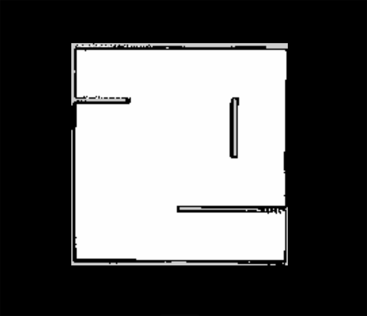
Understanding the Map Output
This is the 2D SLAM map from the maze I created for my robot within Isaac Sim:
The saved map consists of:
isaac_sim_map.yaml:
image: isaac_sim_map.pgm
mode: trinary
resolution: 0.05
origin: [-10.0, -10.0, 0.0]
negate: 0
occupied_thresh: 0.65
free_thresh: 0.25
isaac_sim_map.pgm: A grayscale image where:
- White (255): Free space - safe to traverse
- Black (0): Occupied - obstacles detected
- Gray (205): Unknown - not yet observed
The resolution (0.05) means each pixel represents a 5cm × 5cm area. The origin defines where the map's (0,0) pixel is in world coordinates.
Quick Reference
ROS2 Topics
| Topic | Purpose |
|---|---|
/scan | RPLIDAR laser scans (input to SLAM) |
/odom | Raw wheel odometry |
/odometry/filtered | EKF-smoothed odometry |
/map | Output occupancy grid |
Commands
# Launch mapping (simulation)
ros2 launch ogre_slam mapping.launch.py use_sim_time:=true

# Launch mapping (real robot)
./scripts/launch_mapping_session.sh

# Save map
ros2 run nav2_map_server map_saver_cli -f ~/ros2_ws/src/ogre-slam/maps/my_map

# Check map publishing rate
ros2 topic hz /map
What's Next
With a map saved, the next step is Nav2 integration - but there's a problem. Nav2 sends velocity commands assuming the robot will execute them perfectly. Mecanum wheels are difficult to control precisely. The angled rollers that enable omnidirectional movement also introduce wheel slip, and each motor responds slightly differently. Simple kinematic equations don't account for these real-world factors. None of this crossed my mind when I picked up what looked like a cool robot kit. It is cool - just significantly more complicated than expected.
Part 4 covers training a reinforcement learning policy in NVIDIA Isaac Lab. The neural network learns the robot's actual dynamics through millions of simulated trials - compensating for wheel slip, uneven floors, and motor response differences. Setting up the Isaac Lab environment, defining reward functions, tuning hyperparameters, and iterating through training runs was a significant undertaking.
The trained policy sits between Nav2's velocity commands and the wheel motors, translating "go forward at 0.5 m/s" into the precise PWM signals each wheel needs to achieve that motion. Without it, the robot drifts, overshoots, and struggles to follow planned paths accurately.