Project Ogre Part 1: Building a Mecanum Drive Robot with Jetson Orin Nano
About Project Ogre
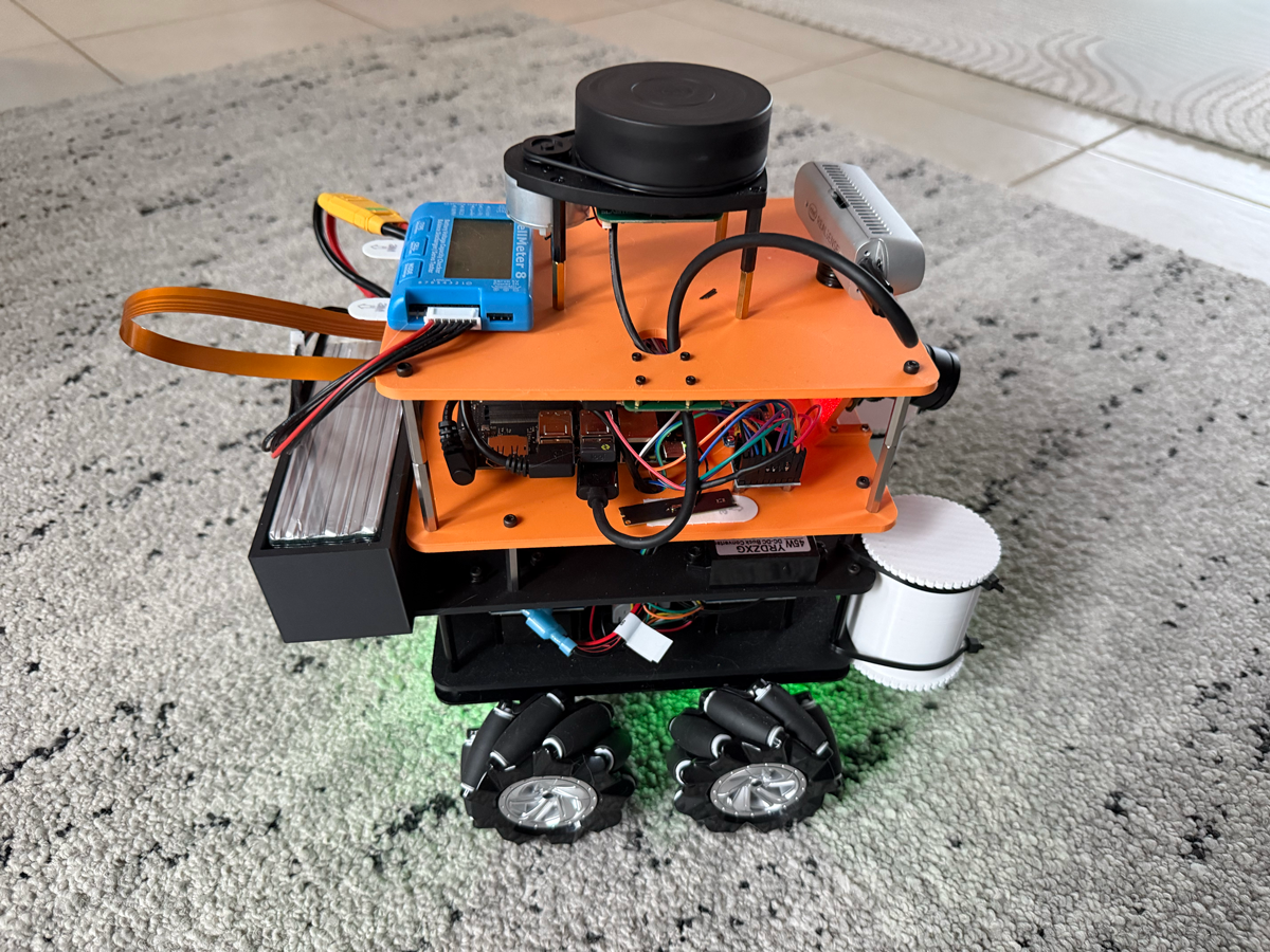
Project Ogre is a mecanum drive robot platform designed for autonomous navigation using ROS2 and NVIDIA's robotics ecosystem. The name comes from the robot's stocky, powerful appearance with its four omnidirectional wheels. This is the first post in a five-part series covering the complete build:
- Part 1: Building the Robot (this post)
- Part 2: Building the Digital Twin in Isaac Sim
- Part 3: SLAM Mapping with slam_toolbox
- Part 4: Training in Isaac Lab
- Part 5: Autonomous Navigation with Nav2
Project Goal: Build a mecanum drive robot powered by the Jetson Orin Nano 8GB Developer Kit, running entirely from a single battery, capable of omnidirectional movement, SLAM mapping, and autonomous waypoint navigation using ROS2 Nav2.
📦 Full Source Code: The teleoperation code we ran on the Jetson Orin Nano to test the motors and camera is available at github.com/protomota/ogre-teleop
Why Mecanum Wheels?
Honestly, I wasn't specifically looking for mecanum wheels. I wanted powerful motors with encoders for a 4-wheel drive robot - something that could power over small bumps and floor transitions where my JetBot would struggle. I was originally planning to just 3D print some standard wheels.
But while browsing for motors, I found a kit that changed my plans: four motors with encoders, four mecanum wheels pre-fitted, and a simple steel platform to build upon. The price was right, and it gave me a solid foundation to work with. So mecanum it was.
The bonus? Mecanum wheels unlock omnidirectional movement. Traditional differential drive robots can only move forward, backward, and rotate. With mecanum wheels, the robot can strafe sideways, move diagonally, and rotate while translating - all thanks to rollers mounted at 45-degree angles on each wheel.
The key insight is that when all four wheels spin together, the angled rollers create force vectors that can be combined to produce motion in any direction:
- All wheels forward → Robot moves forward
- Left wheels backward, right wheels forward → Robot rotates
- Front wheels inward, rear wheels outward → Robot strafes left
This flexibility turned out to be invaluable for navigation in tight spaces, though it does add complexity to both hardware and software.
Hardware Components
Core Computing
- NVIDIA Jetson Orin Nano Developer Kit (8GB) - The robot's brain. The Orin Nano provides significant computing power for running SLAM, Nav2, and sensor processing simultaneously. At 25W power mode, it handles everything smoothly.
Drive System
-
4x 25GA-370 DC Motors with Encoders - These geared motors provide the torque needed to move the robot. Each motor includes a 2 PPR (pulses per revolution) Hall effect encoder for odometry.
-
4x Mecanum Wheels (40mm radius) - The omnidirectional wheels that give the robot its unique mobility. Pay attention to the roller angles - you need two left-handed and two right-handed wheels arranged correctly.
-
PCA9685 Motor Driver - A 16-channel PWM driver controlled via I2C. This handles motor speed control without consuming GPIO pins.
Sensors
-
RPLIDAR A1 - A 360-degree 2D LIDAR scanner. It provides laser scan data for SLAM mapping and localization. The A1 is an excellent entry-level option with 12-meter range at ~8Hz scan rate.
-
Intel RealSense D435 - A depth camera for 3D obstacle detection. While the LIDAR handles 2D mapping, the RealSense provides point cloud data for detecting obstacles below the LIDAR's scan plane (like table legs or stairs).
Physical Dimensions
These measurements are critical for accurate odometry and SLAM:
Body: 200mm (L) x 160mm (W) x 175mm (H)
Wheel Radius: 40mm
Wheelbase: 95mm (front-to-rear axle distance)
Track Width: 205mm (left-to-right wheel centers)
Total Footprint: ~310mm x 205mm x 300mm
Robot Weight: ~5kg (10 lb 15 oz)
The robot sits with its body positioned 20mm above the wheel axle height. The LIDAR is mounted on 65mm posts, placing it at 0.30m above the base_link frame.
System Architecture
The robot is organized into five distinct layers, from sensors at the top to the chassis at the bottom:
┌─────────────────────────────────────────────────────────────────────┐
│                        SENSOR LAYER (Top)                           │
│  ┌──────────────┐   ┌─────────────────────┐   ┌──────────────────┐  │
│  │  RPLIDAR A1  │   │  Intel RealSense    │   │   LiPo Battery   │  │
│  │              │   │       D435          │   │     Monitor      │  │
│  └──────────────┘   └─────────────────────┘   └──────────────────┘  │
└─────────────────────────────────────────────────────────────────────┘
                                 │
                                 ▼
┌─────────────────────────────────────────────────────────────────────┐
│                         LOGIC LAYER                                 │
│  ┌────────────────────────┐  ┌─────────────┐  ┌──────────────────┐  │
│  │   Jetson Orin Nano     │  │   PCA9685   │  │  5V → 3.3V       │  │
│  │         8GB            │  │     PWM     │  │  Logic Level     │  │
│  │    (Main Controller)   │  │    Driver   │  │  Converter       │  │
│  └────────────────────────┘  └─────────────┘  └──────────────────┘  │
└─────────────────────────────────────────────────────────────────────┘
                                 │
                                 ▼
┌─────────────────────────────────────────────────────────────────────┐
│                         POWER LAYER                                 │
│  ┌────────────────────┐   ┌─────────────────────────────────────┐   │
│  │   6S LiPo Battery  │   │   Buck Converters & Power           │   │
│  │                    │   │        Conditioner                  │   │
│  └────────────────────┘   └─────────────────────────────────────┘   │
└─────────────────────────────────────────────────────────────────────┘
                                 │
                                 ▼
┌─────────────────────────────────────────────────────────────────────┐
│                    MOTOR CONTROLLER LAYER                           │
│  ┌──────────────┐ ┌──────────────┐ ┌──────────────┐ ┌────────────┐  │
│  │   Motor      │ │   Motor      │ │   Motor      │ │   Motor    │  │
│  │ Controller 1 │ │ Controller 2 │ │ Controller 3 │ │ Controller │  │
│  │     (FL)     │ │     (FR)     │ │     (RL)     │ │   4 (RR)   │  │
│  └──────────────┘ └──────────────┘ └──────────────┘ └────────────┘  │
└─────────────────────────────────────────────────────────────────────┘
                                 │
                                 ▼
┌─────────────────────────────────────────────────────────────────────┐
│                    STEEL CHASSIS (Base)                             │
│                                                                     │
│    ┌───────────┐                              ┌───────────┐         │
│    │  MECANUM  │                              │  MECANUM  │         │
│    │   WHEEL   │  ════════════════════════    │   WHEEL   │         │
│    │   (FL)    │       25GA-370 Motor         │   (FR)    │         │
│    └───────────┘                              └───────────┘         │
│         ║                                          ║                │
│         ║              STEEL FRAME                 ║                │
│         ║                                          ║                │
│    ┌───────────┐                              ┌───────────┐         │
│    │  MECANUM  │                              │  MECANUM  │         │
│    │   WHEEL   │  ════════════════════════    │   WHEEL   │         │
│    │   (RL)    │       25GA-370 Motor         │   (RR)    │         │
│    └───────────┘                              └───────────┘         │
│                                                                     │
└─────────────────────────────────────────────────────────────────────┘
Motor Layout and Encoder Wiring
The motor arrangement follows the standard mecanum convention:
M4 (FL) --- M1 (FR)
   |    X    |
M3 (RL) --- M2 (RR)
Each motor's encoder connects to GPIO pins on the Jetson. I use BOARD pin numbering:
| Motor | Position | GPIO Pins (BOARD) |
|---|---|---|
| M1 | Front-Right | 7, 11 |
| M2 | Rear-Right | 13, 15 |
| M3 | Rear-Left | 29, 31 |
| M4 | Front-Left | 32, 33 |
The encoder reader uses interrupt-based counting to track wheel rotations. With only 2 PPR, the resolution is quite coarse, which is why sensor fusion (EKF) is essential for usable odometry.
Encoder Calibration: The gear_ratio Challenge
Getting accurate odometry from low-resolution encoders requires careful calibration. The gear_ratio parameter was the most critical value to tune.
The Problem: With 2 PPR encoders, each encoder pulse represents a significant distance traveled. The gear ratio converts raw encoder counts into actual wheel rotations. An incorrect gear_ratio causes massive position drift.
Calibration Process:
- Start with an initial gear_ratio estimate (I started with 50.0)
- Mark the robot's starting position with tape
- Drive exactly 1.0 meter forward using a measuring tape
- Check the reported odometry position
- Calculate the correction factor
When I tested with gear_ratio=50.0, driving 1.0m forward reported 4.483m. The correction:
new_gear_ratio = 50.0 × (4.483 / 1.0) = 224.0
After setting gear_ratio=224.0, the robot reported 1.008m for 1.0m actual travel - an error of just 0.8%.
Odometry Configuration
The odometry parameters live in config/odometry_params.yaml:
wheel_radius: 0.040     # 40mm measured
wheel_base: 0.095       # 95mm measured
track_width: 0.205      # 205mm measured
encoder_ppr: 2          # Hall sensors: 2 PPR
gear_ratio: 224.0       # Calibrated for 25GA-370 motors
publish_rate: 50.0      # Hz
The covariance matrices are set high because the 2 PPR encoders are inherently noisy:
pose_covariance_diagonal: [1.0, 1.0, 0.0, 0.0, 0.0, 1.0]
twist_covariance_diagonal: [0.5, 0.5, 0.0, 0.0, 0.0, 0.5]
EKF Sensor Fusion
With only 2 PPR encoders, raw odometry is too noisy for SLAM. The robot_localization package implements an Extended Kalman Filter (EKF) that smooths the odometry data.
The data flow:
Raw Encoders → odometry_node → /odom (noisy)
                                   ↓
                            ekf_filter_node (smoothing)
                                   ↓
                          /odometry/filtered (clean)
                                   ↓
                        SLAM & Nav2 (accurate mapping/navigation)
The EKF combines the noisy encoder measurements with a motion model, weighting each based on configured covariances. The result is much smoother position estimates that SLAM can actually use.
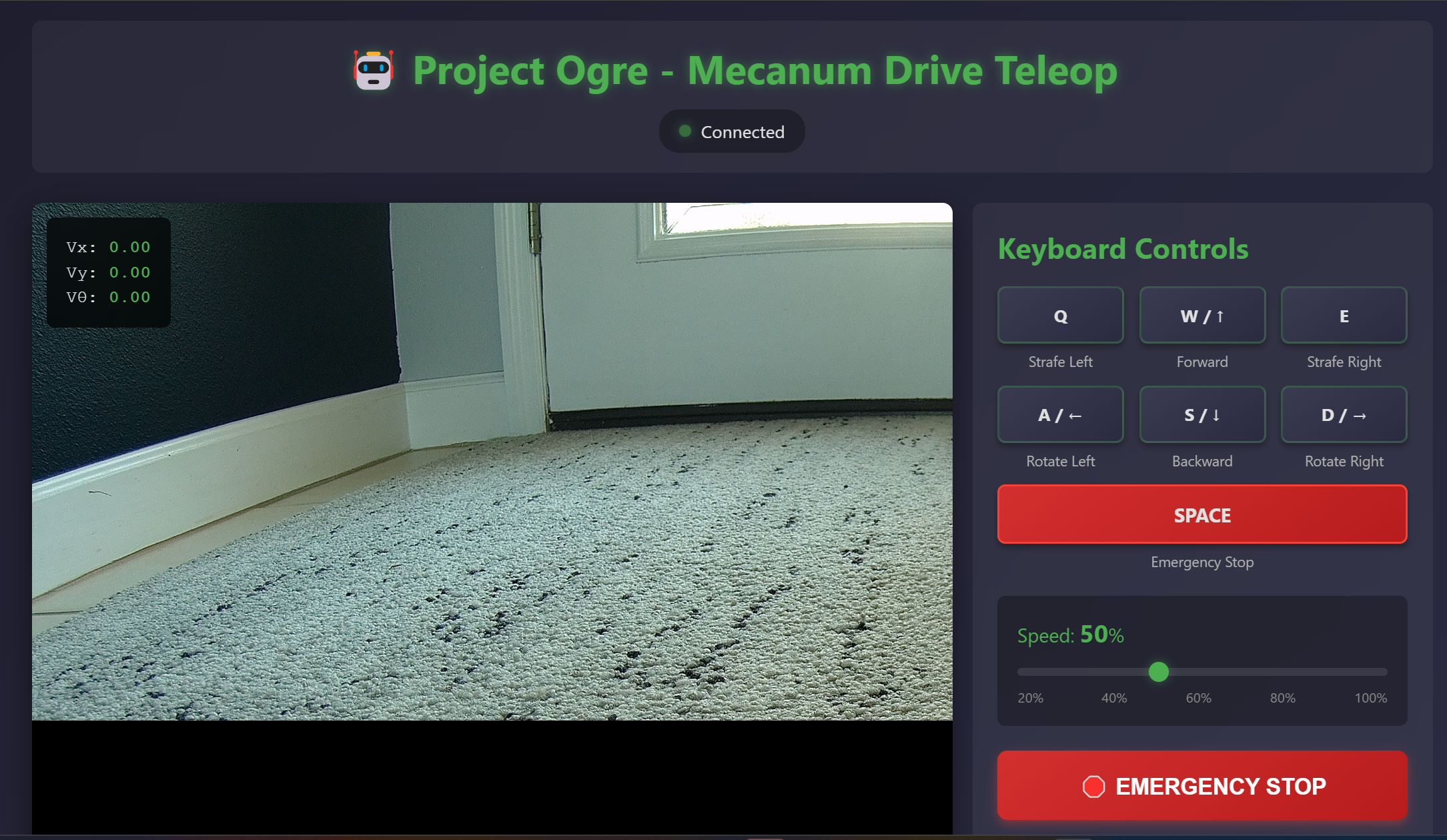
Flask Teleoperation Server
Before diving into autonomous navigation, I needed a way to manually control the robot and view the camera feed. The solution was a Flask-based web interface that runs on the Jetson.
Why Web-Based Control?
A web interface has significant advantages over traditional approaches:
- Device agnostic - Control from any phone, tablet, or laptop on the network
- No installation - Just open a browser and navigate to the robot's IP
- Visual feedback - Live camera stream alongside controls
- Development friendly - Easy to extend with new features
Architecture
The Flask server exposes two main endpoints:
Camera Stream (/video_feed)
- MJPEG stream from the RealSense RGB camera
- Runs at ~15 FPS to balance quality and bandwidth
- Uses OpenCV to capture and encode frames
Motor Control (/cmd_vel)
- Accepts POST requests with velocity commands
- Translates to ROS2 Twist messages
- Implements dead zone for joystick drift
Web Joystick
The frontend uses a virtual joystick library that maps touch/mouse input to velocity commands:
- Vertical axis → Linear X velocity (forward/backward)
- Horizontal axis → Angular Z velocity (rotation)
- Smooth ramp-up/down for natural feel
Running the Server
cd ~/ros2_ws/src/ogre-teleop
python3 app.py
Then open a browser to http://<robot-ip>:8080. The interface shows the camera feed with an overlaid joystick control.
This web interface proved invaluable for testing motor calibration, verifying camera mounting angles, and generally getting a feel for how the robot handles before writing autonomous code.
TF Frame Structure
ROS2's TF system tracks the relationship between coordinate frames. For Project Ogre on the real robot:
map (from slam_toolbox or amcl)
  └─ odom (from EKF or odometry_node)
      └─ base_link (robot center at wheel axle height)
          ├─ laser (RPLIDAR: 0.30m up, 180° rotated)
          └─ camera_link (RealSense D435: 0.15m forward, 0.10m up)
Note that the LIDAR is mounted with a 180° rotation. This is common - just ensure your URDF/launch files account for it.
Power Considerations
The entire robot runs from a single 5000mAh 6S LiPo battery (~24V nominal). Three buck converters distribute power to different subsystems:
- 24V → 12V: Powers the Jetson Orin Nano (accepts 9-20V input)
- 24V → 9V: Powers the motor controllers
- 24V → 5V: Powers the 5V rail for logic-level components
This single-battery approach keeps the robot compact and simplifies charging. The 6S LiPo provides plenty of headroom for the Jetson's power demands while the buck converters ensure each subsystem receives clean, regulated voltage.
Weight Distribution
One challenge I didn't anticipate was weight balance. The 6S LiPo battery is heavy and sits at the rear of the robot, which created an uneven weight distribution. Without counterbalancing, too much torque to the motors would cause the robot to tip backward and fall on its back.
My solution was to 3D print small cylindrical barrels and fill them with fishing weights (lead sinkers). These counterweights mount at the front of the chassis to balance out the battery's mass. It works, but it's not elegant.
In hindsight, I would have tried harder to position the battery at the robot's center of mass from the start. Planning for weight distribution early in the design process would have saved me from adding dead weight to compensate later. Lesson learned for the next build.
What's Next
With the robot built and calibrated, Part 2 covers building an accurate digital twin in NVIDIA Isaac Sim. Creating a simulation environment first would have been the smarter approach, but I was too eager to get hardware running. The digital twin lets us:
- Test code changes without risking hardware damage
- Iterate faster with instant simulation resets
- Develop navigation algorithms in a controlled environment
- Debug issues that are hard to reproduce on real hardware
The simulation uses the same ROS2 interface as the real robot, so the same code runs in both environments.